
Resources
3-Axis vs 5-Axis Injection Molding Robot Supplier Guide

A 3-axis vs 5-axis injection molding robot comparison should start with the required motion after the part leaves the mold. A 3-axis robot can suit direct take-out and defined placement, while a 5-axis robot can support additional orientation and more complex placement. This supplier guide explains the machine, mold, part, EOAT and downstream information buyers should prepare before selecting a servo robot for injection molding.
Technical review: KEFAN Automation Engineering Team
Buyer summary
Select between a 3-axis and 5-axis injection molding robot by mapping the complete pickup and placement path. Use the machine interface, mold-open window, part and runner geometry, combined part and EOAT weight, required strokes, target cycle and downstream task as the decision inputs. A 3-axis system is commonly evaluated when the part follows a direct take-out and defined placement path. A 5-axis system is evaluated when additional wrist motion, orientation or more complex placement is required. Axis count alone does not determine suitability; the supplier should confirm the whole sequence before quotation.
What 3-axis and 5-axis mean in robot selection
A linear robot for injection molding uses coordinated movements to enter the mold area, pick a part or runner and transfer it to the next position. The axis configuration determines the available motion, but the practical question is whether that motion can complete the defined production sequence.
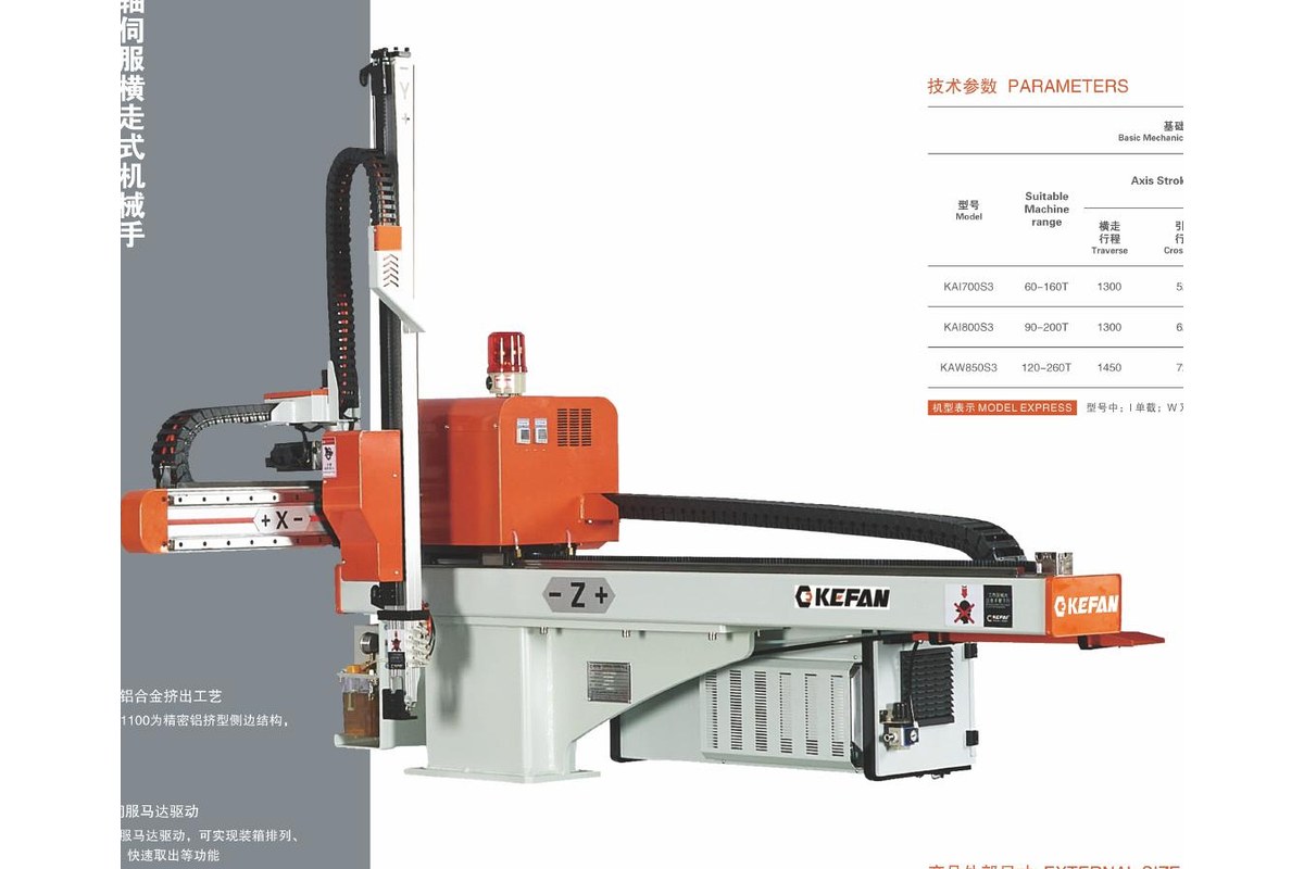
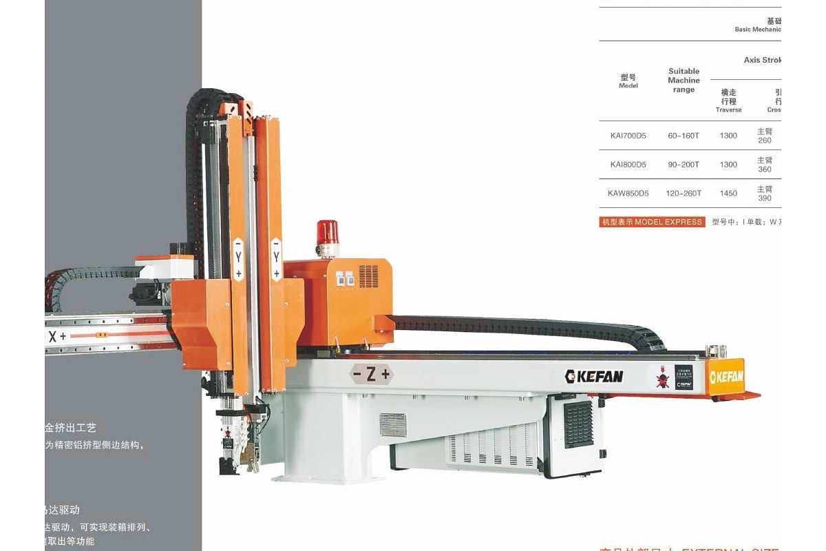
A 3-axis injection molding robot is commonly considered for vertical, traverse and crosswise movement in direct take-out and placement applications. A 5-axis injection molding robot adds motion that can support extra orientation and a more complex path. The exact configuration must still be checked against the robot design, EOAT and project layout.
3-axis vs 5-axis injection molding robot comparison
| Selection point | 3-axis robot | 5-axis robot |
|---|---|---|
| Typical task | Direct take-out and defined placement | Take-out with additional orientation or more complex placement |
| Part orientation | Suitable when the required orientation can be achieved by the configured path and EOAT | Consider when the part must change orientation within the handling sequence |
| Downstream process | Defined placement to a fixture, conveyor or drop position | More complex positioning for inspection, stacking, inserts or other downstream tasks |
| Engineering inputs | Machine interface, mold-open window, load, strokes, cycle and placement point | The same inputs plus the required orientation and complete motion sequence |
| Quotation decision | Confirm that the direct path completes every required task | Confirm that added motion is necessary for the real application |
This table describes common evaluation logic, not a universal rule. The final selection depends on the actual robot construction and application data supplied for engineering review.
Start with the machine and mold-open window
Provide the injection molding machine brand, model, clamping force and communication interface. The supplier also needs the available mold-open stroke, robot entry direction, mounting space and the time window in which the robot must enter, grip the part and leave the mold area.
Machine tonnage helps narrow the initial range, but it does not define the complete robot. Mold dimensions, release direction, part location and the required pickup path can change the necessary vertical, traverse and crosswise strokes.
Check part, runner and EOAT requirements
The payload calculation should include the molded part, runner and complete end-of-arm tooling. Part dimensions, material, surface limits, number of cavities and pickup points influence the gripper design. Vacuum cups, fingers, sensors and custom fixtures can also affect the required motion and orientation.
Review custom EOAT and robot gripper options together with the axis decision. A more complex wrist is not a substitute for correctly designed tooling, and a simple motion path still requires an EOAT concept that can release the part safely at the destination.
Representative models for technical discussion
| Suitable IMM | 3-axis model | 5-axis model | Traverse | Vertical | Maximum load |
|---|---|---|---|---|---|
| 60-160T | KAI700S3 | KAI700D5 | 1300 mm | 700 mm | 5 kg |
| 120-260T | KAW850S3 | KAW850D5 | 1450 mm | 850 mm | 6 kg |
| 260-400T | KAW1100S3 | KAW1100D5 | 1850 mm | 1100 mm | 8 kg |
Reference data from the current KEFAN robot specification sheet. Specifications and availability are reconfirmed for each quotation.
These models provide a starting point for technical discussion. The supplier should verify strokes, load, machine interface, EOAT and motion sequence before recommending a final configuration.
Match the robot to the downstream task
Part removal is only one step in an automation cell. The robot may need to place parts on a conveyor, load a fixture, present a surface for inspection, stack products, load trays or connect with packaging equipment. Define the required final position and orientation before choosing the axis configuration.
If the project includes several connected processes, review custom injection molding automation solutions and relevant injection molding applications. The robot, EOAT, guarding, controls and downstream equipment should follow one agreed sequence.
Information to send the robot supplier
- Injection molding machine brand, model, clamping force and interface
- Mold dimensions, mold-open stroke, cavities and release direction
- Part and runner drawings, material, dimensions and weight
- Pickup points and proposed EOAT concept
- Required vertical, traverse and crosswise strokes
- Target cycle and available mold-open window
- Placement position and required final orientation
- Downstream inspection, conveying, stacking or packaging task
- Available mounting space, floor space and guarding conditions
Buyers comparing quotations should also confirm the included engineering and delivery scope. The injection molding robot cost guide explains the main price and quotation factors.
Frequently asked questions
Is a 5-axis injection molding robot always better than a 3-axis robot?
No. A 5-axis robot is useful when the application needs additional orientation or a more complex placement path. A 3-axis robot can be the suitable choice when direct take-out and defined placement complete the required sequence.
Can the same injection molding machine use either configuration?
Possibly, but machine tonnage alone cannot confirm suitability. The supplier must review the machine interface, mold-open window, strokes, part and EOAT weight, pickup path, cycle and downstream task.
What data does a robot supplier need for selection?
Provide the machine model and clamping force, mold and part details, mold-open window, combined part and EOAT weight, pickup points, required strokes, placement position, target cycle and downstream process.
Request 3-axis or 5-axis robot selection
Compare KEFAN’s broader injection molding robot range, then send the available machine, mold, part and process data for engineering review. The recommendation can identify the required axis configuration, strokes, load and EOAT assumptions before quotation.
Request injection molding robot selection and a custom quote