
Side-Entry Robot for Injection Molding Automation
This side-entry robot application is designed for injection molding cells where the robot must access the mold from the side, remove the molded part and transfer it within a controlled production sequence.
When a Side-Entry Layout Fits
A side-entry layout can be considered when the machine arrangement, mold access and downstream station make a lateral transfer path practical. The final selection depends on the machine geometry, mold opening, part release direction and required placement.
Project Scope
- Side-entry robot motion into and out of the mold area
- Part take-out matched to the cavity layout and release direction
- EOAT contact points, vacuum or pneumatic functions as required
- Controlled transfer to a conveyor, inspection, packing or other downstream station
Integration Review
KEFAN engineers review the injection molding machine brand, model and clamping force, side-access clearance, mold-open window, part dimensions and weight, cavity arrangement, target cycle and placement method. Guarding, safety sensors, machine signals and maintenance access are also included in the integration discussion.
What to Confirm for a Similar Project
- Available side access and the machine layout drawing
- Part dimensions, material, weight and acceptable gripper contact areas
- Mold opening, release direction, cavity layout and required pickup pattern
- Target take-out sequence, downstream equipment and floor-space limits
Share these details with KEFAN engineering for a side-entry robot selection and quotation review. You can also compare the broader side-entry injection molding robot range and injection molding robot solutions.
Watch the Project Video
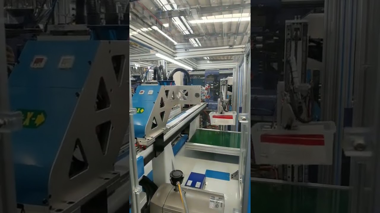
Discuss your side-entry automation project with the KEFAN team and include your machine, mold, part and target-cycle information.
Project facts that are publicly confirmed
| Field | Confirmed information |
|---|---|
| Industry | Injection molding automation using a side-entry robot layout. |
| Production line | Side-access mold take-out and controlled transfer to a downstream station; exact line count and site details are not publicly disclosed. |
| Machine and mold | Machine geometry, clamping force, side-access clearance, mold-open window, part dimensions, weight, cavity arrangement and release direction are engineering inputs; project values are not published. |
| EOAT | EOAT contact points and vacuum or pneumatic functions are considered as required; actual tooling design is not publicly disclosed. |
| Interfaces | Machine signals, guarding, safety sensors, maintenance access and downstream equipment are part of the review. |
| Commissioning and acceptance | Layout and integration review are described; project-specific acceptance criteria and signed results are not publicly disclosed. |
| Customer permission | No customer identity or permission statement is published. Customer-identifying media, logos, testimonials or results require written approval. |
Disclosure boundary: The page describes selection criteria and integration scope without claiming unverified production performance.